


Design Requirements
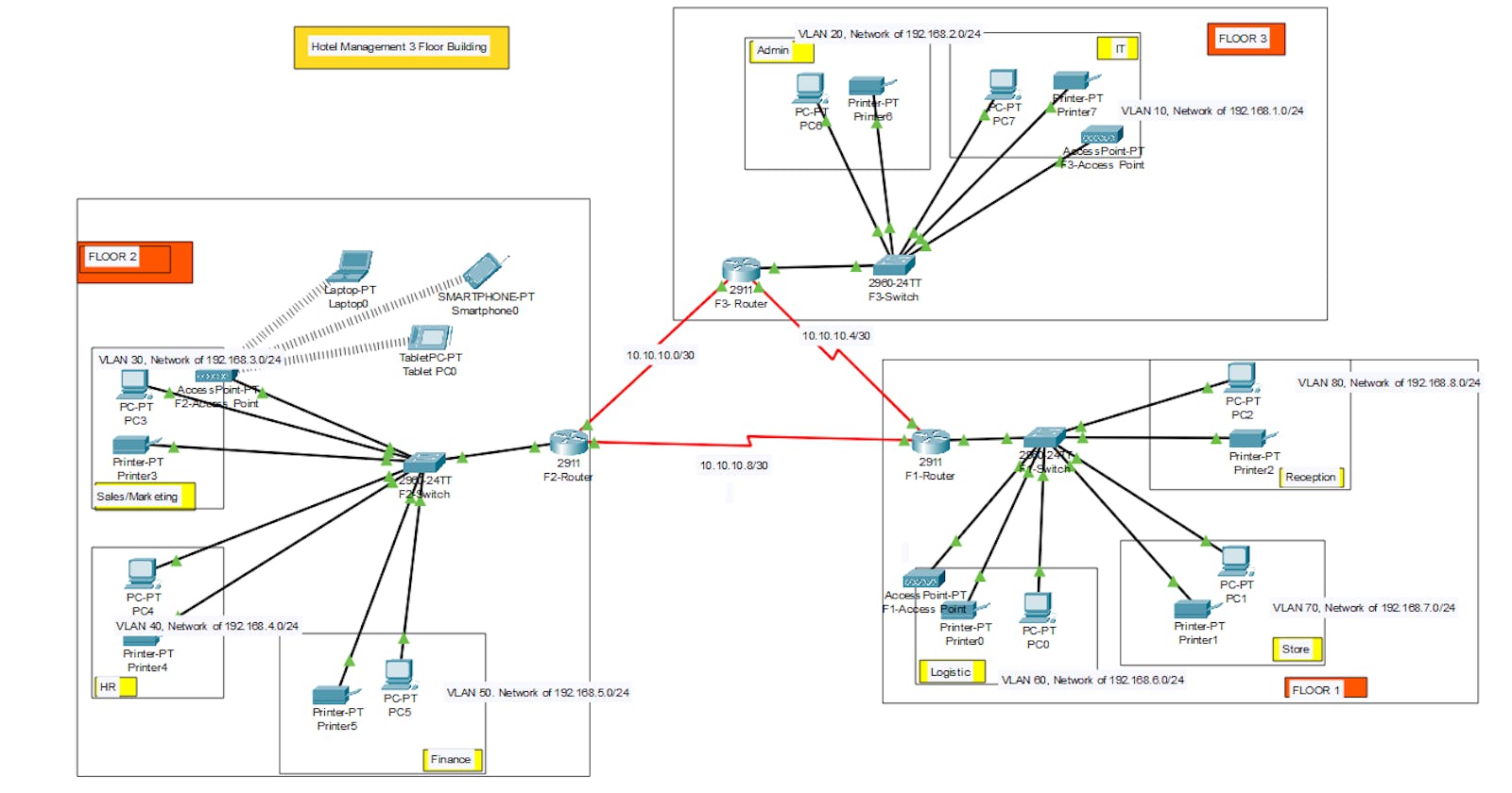
As a part of your end year networking project, you are required to design and implement VIC Modern Hotel network The hotel has three floors; in the first floor there three departments (Reception, store and Logistics), in the second floor there are three departments (Finance, HR and Sales/Marketing), while the third floor hosts the IT and Admin Therefore, the following are part of the considerations during the design and implementation
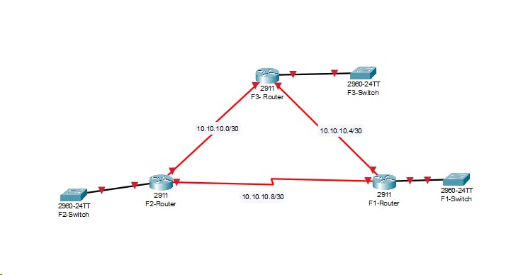
There should be three routers connecting each floor (all placed in the server room in IT department).
All routers should be connected to each other using serial DCE.
The network between the routers should be 10.10.10.0/30,10.10.10.4/30,10.10.10.8/30
Each floor is expected to have one switch (placed in the respective floor).
Each floor is expected to have WIFI networks connected to laptops and phones.
Each department is expected to have a printer.
Each department is expected to be in different VLAN with the following details
1st Floor;
Reception- VLAN 80, Network of 192.168.8.0/24
Store- VLAN 70, Network of 192.168.7.0/24 Logistics- VLAN 60, Network of 192.168.6.0/24
2nd Floor;
Finance- VLAN 50. Network of 192.168.5.0/24
HR- VLAN 40, Network of 192.168.4.0/24 Sales- VLAN 30, Network of 192.168.3.0/24
3rd Floor;
Admin- VLAN 20, Network of 192.168.2.0/24
IT- VLAN 10, Network of 192.168.1.0/24
Use OSPF as the routing protocol to advertise routes.
All devices in the network are expected to obtain IP address dynamically with their respective router configured as the DHCP server.
All the devices in the network are expected to communicate with each other.
Configure SSH in all the routers for remote login
In IT department, add PC called Test-PC to port fa0/1 and use it to test remote login
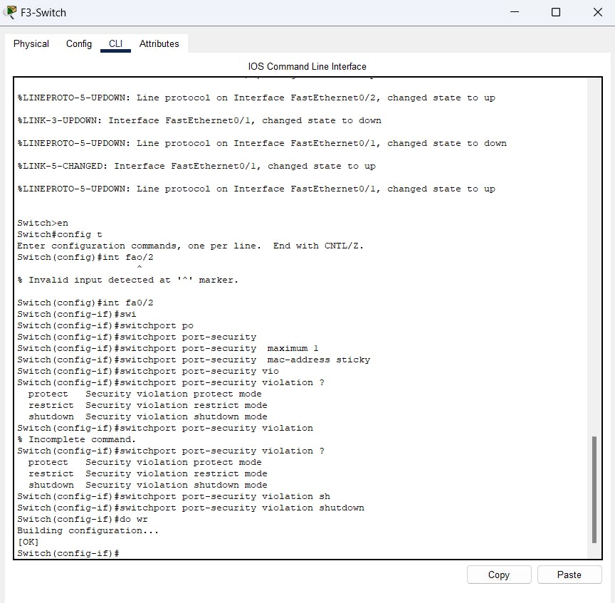
Configure port security to IT-dept switch to allow only Test-PC to access port fa0/1 (use sticky method to obtain mac-address with violation mode of shutdown.
Designing begins here,
Take the 3 router for three floor, connecting them with DCE cable, there needs serial port for DCE cables, Add HWIC-2T serial port to all router.
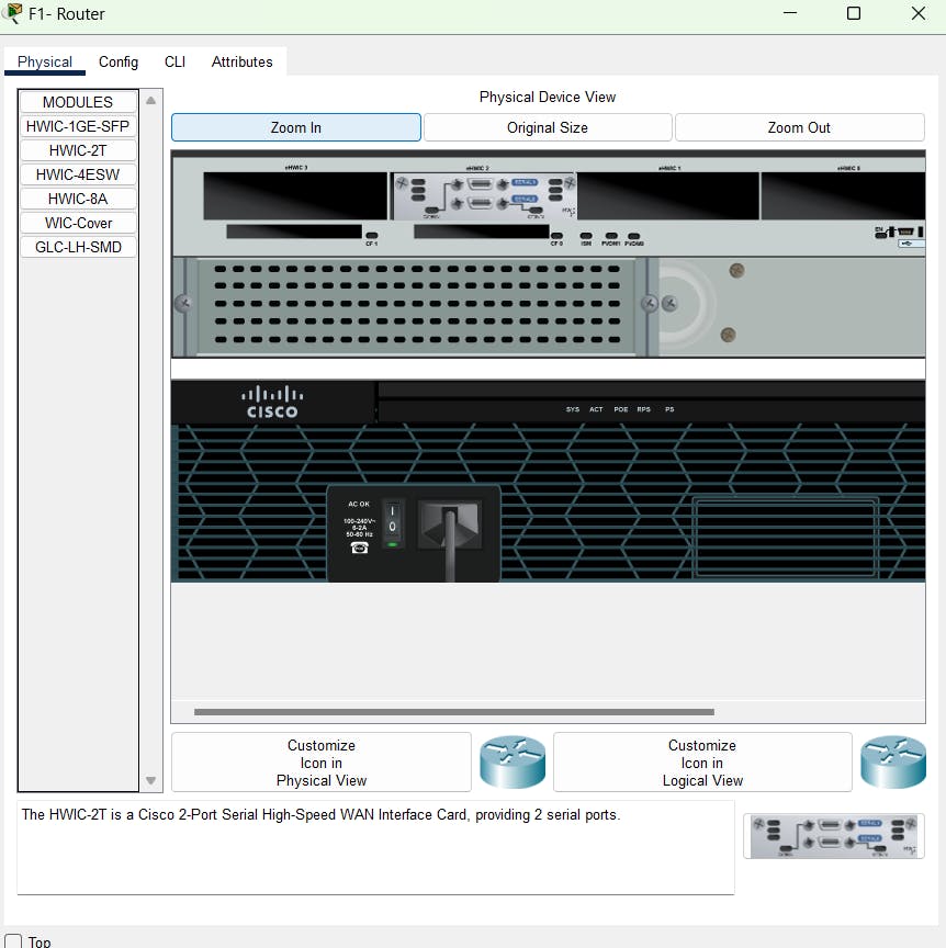
There after serial port will be available for router
Assign network between the router and add switch's to each floor
Connect PC and printer to switches according to requirement as department wise with automatic cable.
Create VLAN for each department within the define network

Now the configuration of all the devices,
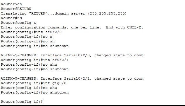
Configure No shutdown on all router (E.g. F3-Router)
As router are connected using serial DCE, For communication there is need to define the **Clock Rate (**Prefer as 64000)DDDD(E.g. F3-Router)

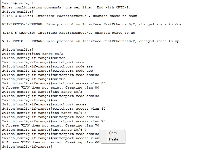
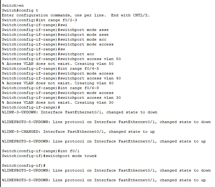
Configure the VLAN on all switch's (E.g. For F1-
switch )
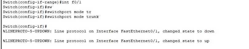
PC and Printer interfaces as access, and router to switch interface as trunk port.
Configuring as a trunk port
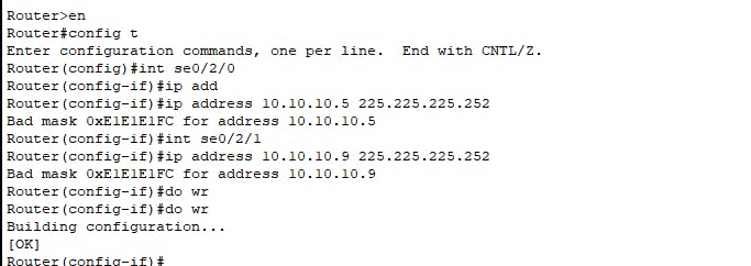
Configuring IP address to DCE routers interface
As interface network is 10.10.10.1, so 10.10.10.2 and 10.10.10.3 will end host IP
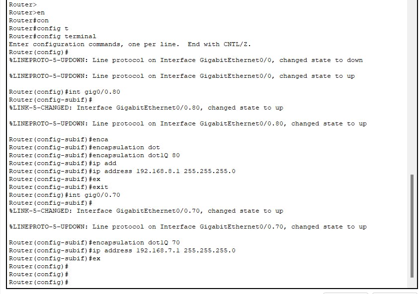
As we have multiple VLAN there is need to configuring the Inter VLAN routing and DHCP server for network assigning, for that we will create sub interfaces and assign them VLAN and IP addresses, that IP address will act as default gateway for respective VLAN. (E.g. All the process is for one router F1, do these for all router)

VLAN and IP address are assign, now it's time to config DHCP,
Enable the DHCP services, create pool for each VLAN, assign the limits of range, also the default gateways (Default router) that we had created in above step10, and configure the DNS server.

Results of PC1 of Reception department.
You can check Inter VLAN routing using Ping command of PC's

Now F1 cannot communicate to F2 and F3 vice versa.
To make it possible, we have configure routing protocol on the routers. That is OSPF, So that they can advertise the neighbor's, For example F1 router has 5 neighbor, do same for all router.

Result are here PC 6 is communicating with Sales department printer. As OSPF is configure successfully.

Now WIFI configuring, Adding devices to the network design Phone , Tablet and Laptop and change the port of laptop WPC300N (WIRELESS PORT)'

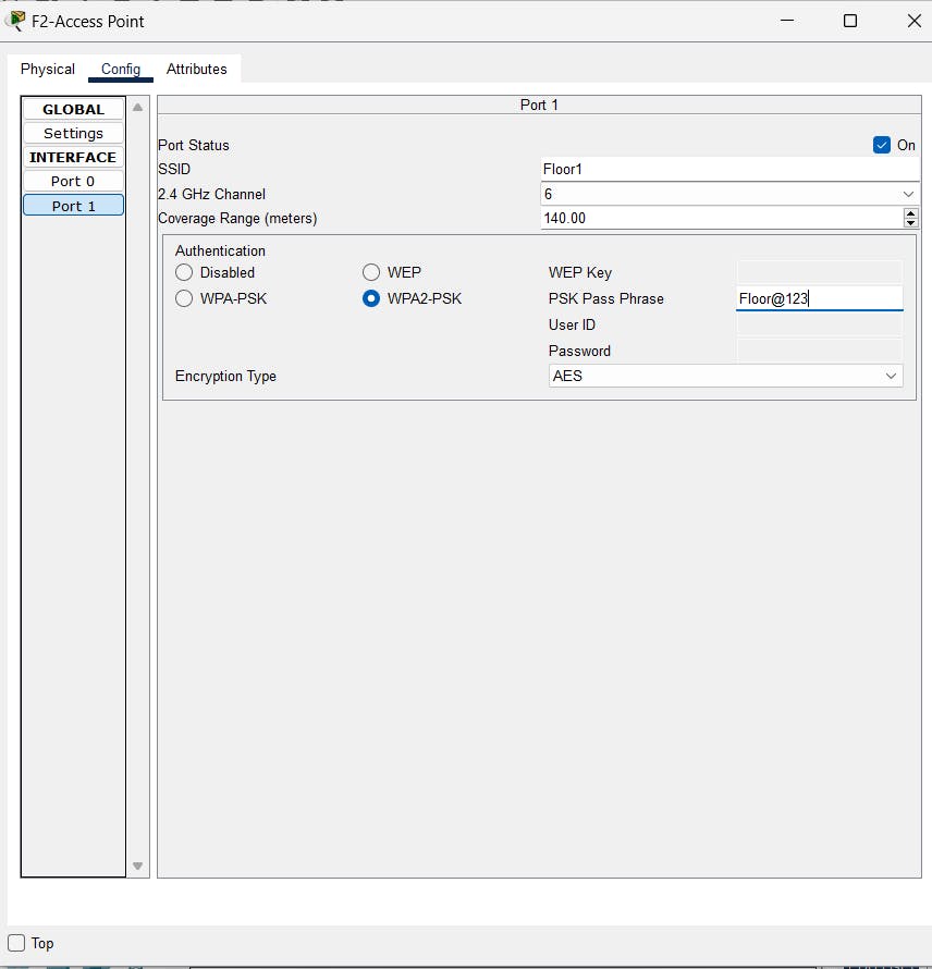
And configure the Access Point
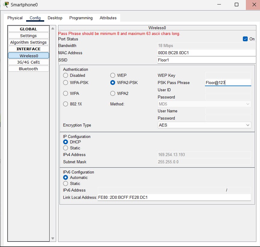
Now Added devices are not connected to Access Point of Floor 2, To connect them config each devices to wireless connection.
For Laptop


Insert Password that is set for access point.
For Tablet
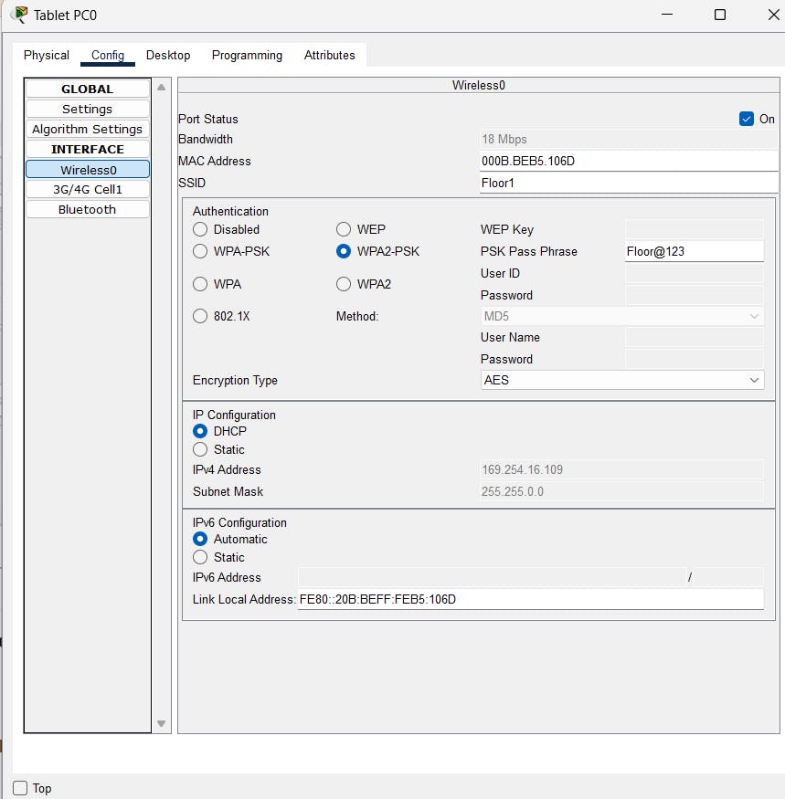
Results are,

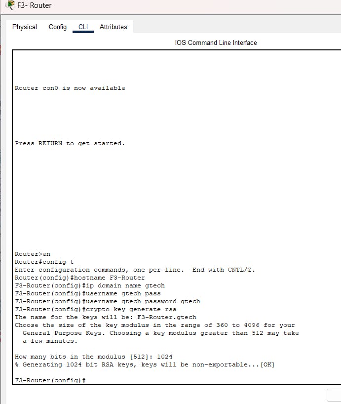
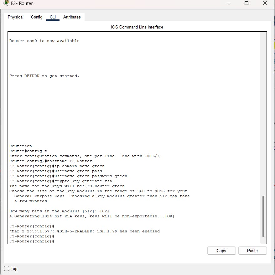
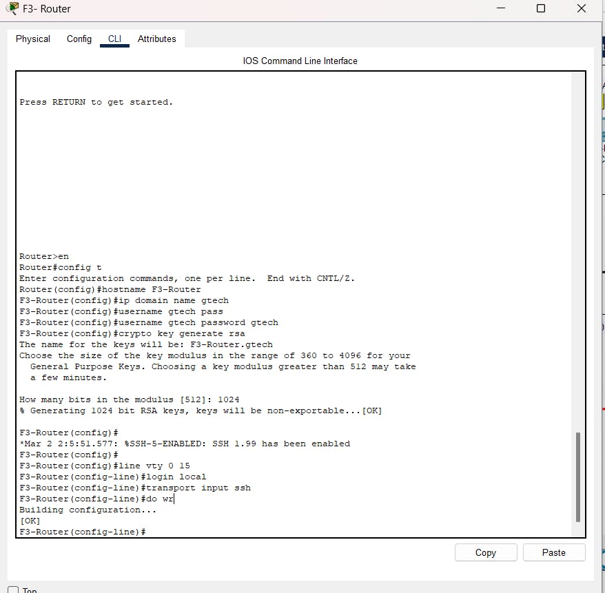
Configuring SSH on router for remote login.
First of all configure the hostname of router, Domain name, username & Password and Crypto Keys for all routers (E.g. for F3-Router)
(VTY is virtual teletype) VTY is a virtual port and used to get Telnet or SSH access to the device. VTY is solely used for inbound connections to the device. The abstract “0 – 4” means that the device can allow 5 simultaneous virtual connections which may be Telnet or SSH.
For router F2


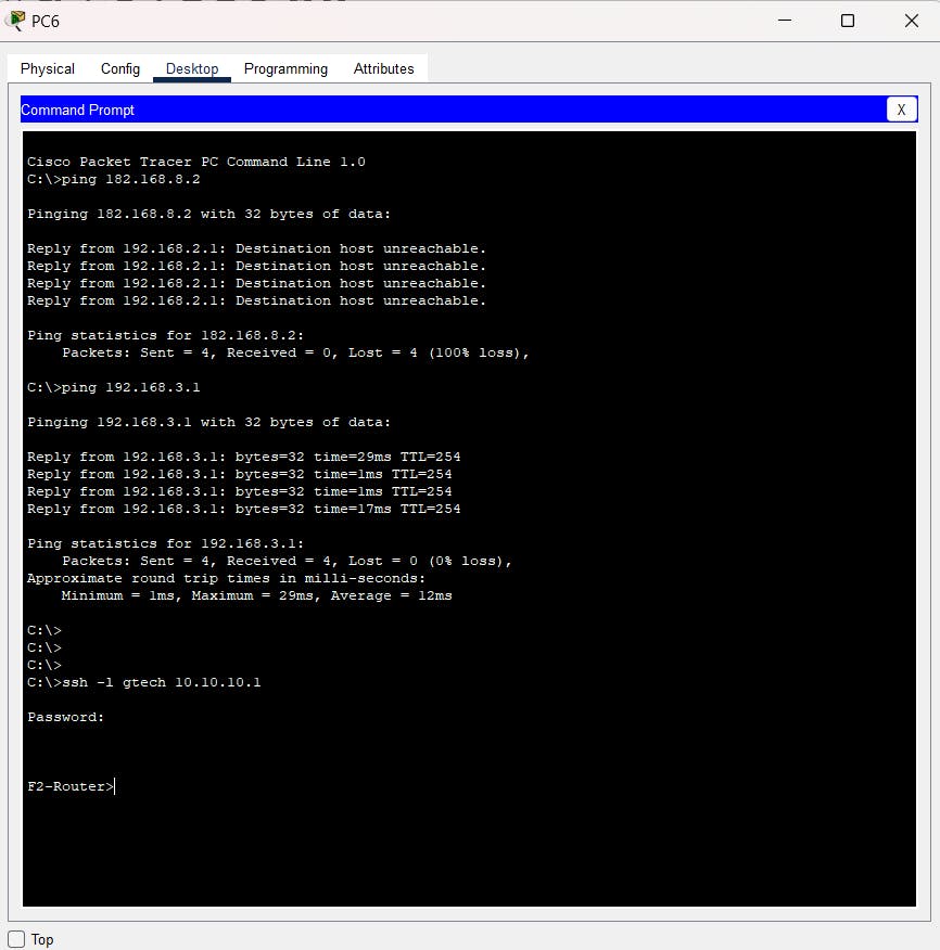
Now testing the remote login.
ssh -l <username> <IP address of interface/sub interface>and insert password
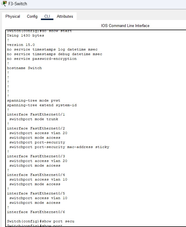
Configuring port security on the switch interfaces
Results

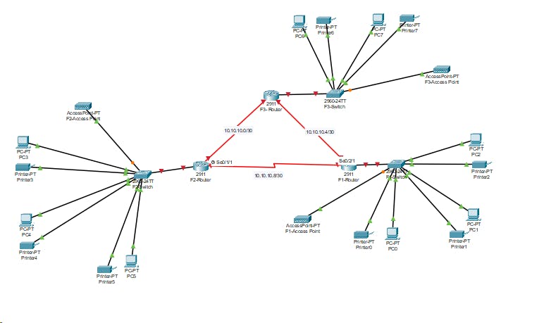
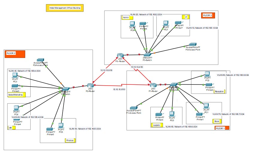
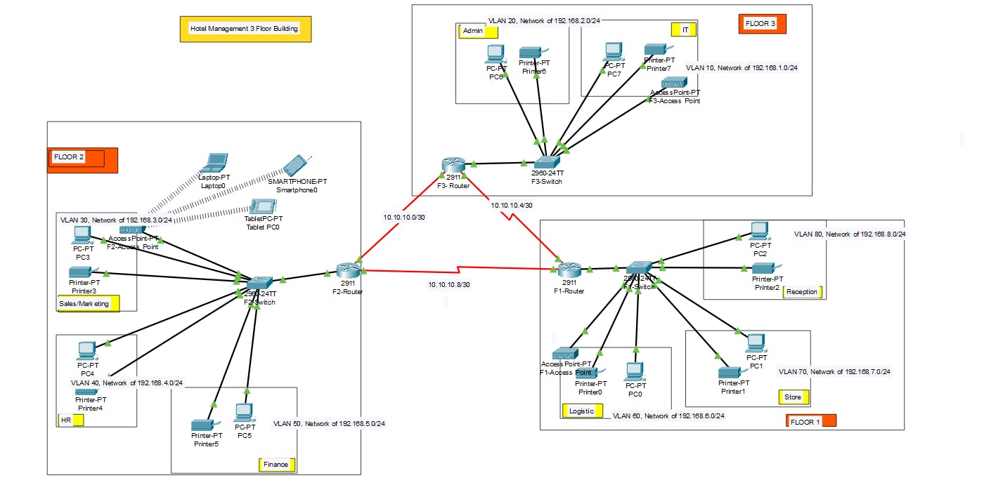
Final Network design for the project is :
Here is link of Cisco Packet tracer file